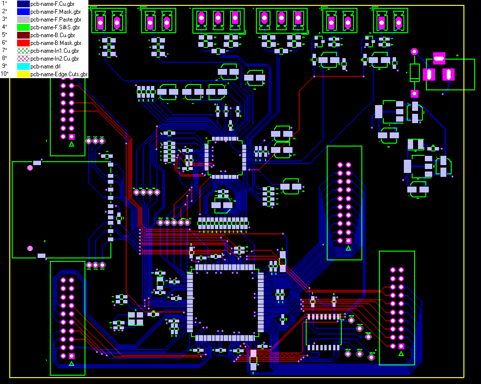
- #Pcb Gerber Viewer Full Graphical Control#
- #Pcb Gerber Viewer How To Generate Gerber#
- #Pcb Gerber Viewer Software You Used#
Pcb Gerber Viewer Full Graphical Control
The PADS PCB Viewer allows the user to load any PADS Logic or PADS Layout database and have full graphical control to view these designs. Free PADS Standard & PADS Standard Plus PCB Viewer. Light, PCB Artist, PCB, and many more programs. Pcb viewer free download - Gerber PCB Viewer.
You have data in ODB++, IPC-2581, GenCad or any other data format and want to visualize itGerbv is a viewer for Gerber RS-274X files, Excellon drill files, and CSV pick-and-place files. Upload your Gerber designs to view online. PCB Investigator backend functionality. Significant improvement of the measuring function. Opt for the free Online Gerber Viewer and benefit from numerous innovations. We here at hobby level and present a lot of free dissemination work.

Pcb Gerber Viewer Software You Used
Further negotiations and requests will consume your time and affect the manufacturing process significantly.Still, even if both of you use the same design software, generating Gerber files by yourself is crucial in preventing possible errors resulting from different terms.Hence, to ensure the production process proceeds as planned and your end products are reliable, you should learn to make Gerber files independently. A comprehensive PCB information outlines multiple procedures, such as machining processes that you should carry out and others.First, you can barely ensure that your manufacturer uses the same software you used in the design process.In case your manufacturer specifies that they are using different software, you should make Gerber files by yourself. Besides, there will be templates containing different drill holes, their position, and use.Mostly, surface riding and overlaid holes come in various templates. A picture of the copper layer to be placed on the upper part of the board.There would be two templates for the solder mask and silkscreen pictures for your manufacturer to include on the circuit board's lower and upper parts. A picture of the copper layer to be placed on the lower part of the board.
Pcb Gerber Viewer How To Generate Gerber
Without further ado, let us dive into the process of generating Gebers in Kicad!First, open your Kicad project. What you need to do is to choose the appropriate layers and make the DRILL file. We will discuss how to generate Gerber files using Kicad, Altium Designer, and Eagle software.Generally, it is much easier to create Gerber files via Kicad than other circuit board design tools. Additionally, regarding the two layers containing similar design information, you should still generate your Gerber files one by one to avoid any mix-up.It is essential to realize that various PCB design tools have distinct operations steps of Gerber file creation.
Then press the Drill File tab, as illustrated below.That is it. With this in mind, tick the Suppress leading zones and Minimal header boxes. The board outline layer- pcbname.GML/GKOAnother critical point to note is that you should create the drill for manufacturing purposes before closing your plot panel. The solder masks the lower layer- pcbname.GBS The solder mask upper layer- pcbname.GTS Likewise, press the Plot tab to produce the corresponding layers.The essential layers you need for a 2-layer circuit board are:
Upon adding the file, you can think of the manufacturing documents you need to create and its formats.As an illustration of these points, you can refer to the diagram below. The first thing you should do is to introduce a new OutJob template to your circuit board project. Besides, you should fill out the document about your board features, such as size.You can check this video for a comprehensive illustration of how to export Gerber files in Kicad. Zip FileLastly, you should compress your files in one .zip file. If everything is OK, you can now send your Gerber file to your PCB manufacturer.Your board should resemble the image below.Compress your Files in a Single. Click the GerbView and confirm the shape and configuration of your PCB.

As a professional, check your Gerber files to ensure there are working correctly. To complete this process, hit the Generate Content button on the right side of your workspace.Wow, you have successfully generated your Gerber files. But if you have powered any other Viator drill element, such as blind Vias, you will access their corresponding options.In the diagram below, we have enabled all the Gerber templates and other manufacturing documents you should export. Naturally, this tab contains a top and bottom layer. If you had this button to choose the matching drill layers, you would adapt to a Gerber template. They include electrical, mechanical, and silkscreen layers.
If your .brd file has milling designs, ensure you incorporate an additional outline layer before ticking the Miling Dimension.Now, follow these steps to generate Gerber files for your PCB manufacturing.Running the drilling command is the first step in generating Gerber files in Eagle.To achieve this, navigate to the File section and click Run ULP. This is because, by default, you will only generate the upper silkscreen layer.Therefore, if your circuit board contains a two-sided silkscreen, you should also introduce the lower layer. In this section, you will learn how to send Gerber documents from the Eagle .brd file to your PCB manufacturer.Before creating Gerber files, the first thing to remember is to check whether the silkscreen lies on a single or double side. Therefore, you should export your Gerber templates directly to a circuit board fabrication.
Now proceed to the File section, select Open and click the Job button to access the Open CAM Job command. Cam dialog box.Then, press the Process Job tab to create the conforming drill file.Remember, we are still in the CAM Processor dialog panel.


 0 kommentar(er)
